
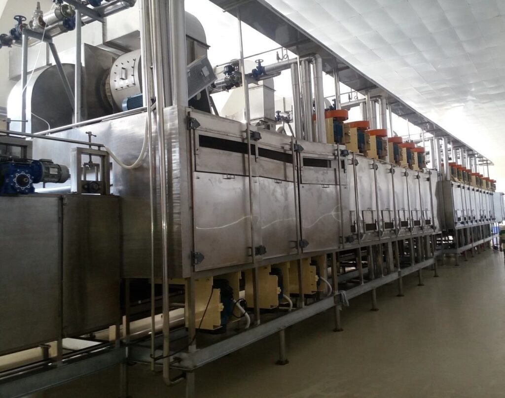
What should drying plant automation do? Hold product moisture on target while feed and weather change, protect people and equipment with interlocks, and record the data that prove performance and energy use. A PLC (programmable logic controller) runs the control loops and interlocks. An HMI (operator screen) or SCADA (supervisory control and data acquisition) system adds recipes, trends, alarms and reports. The right level depends on the dryer, the number of products and how much data the owner needs. This guide sets out what to control on belt, fluid bed and spray dryers, what to put in the control philosophy, how to test the system, and what changes for machines going to Europe from January 2027. It is for project engineers, plant managers and investors specifying a new drying line.
Why is dryer control system design getting more attention now?
Because connected control systems now fall under machinery safety law in some markets. The EU Machinery Regulation (EU) 2023/1230 applies from 20 January 2027. It adds requirements to protect safety-related software and data against corruption, and to make control systems withstand reasonably foreseeable malicious attempts that could cause a hazardous situation.
The European Commission confirms the 20 January 2027 application date, and that machinery placed on the EU market before then must comply with the Machinery Directive 2006/42/EC (European Commission, Machinery). The relevant points are in Annex III, sections 1.1.9 and 1.2.1 (EUR-Lex text). Buyers outside the EU are not bound by it, but the same ideas, such as controlled remote access, logged software changes and protected safety functions, are good practice anywhere. We do not imply that any particular dryer or supplier complies.
What should be controlled on each type of dryer?
The variables that set product moisture and safety. On belt dryers: zone air temperature, belt speed and bed depth. On fluid bed dryers, inlet air temperature, airflow and vibration or weir setting. On spray dryers, inlet temperature and outlet temperature, with outlet usually held by adjusting the feed rate. Each needs a measurement, an actuator and a control strategy.
| Dryer type | Main controlled variables | Typical actuator | Key interlocks |
|---|---|---|---|
| Belt, band or mesh belt dryer | Zone air temperature, belt speed, bed depth, exhaust humidity or temperature | Steam or fuel valve, drive speed, feed spreader, exhaust damper | Fan proven before heat; heat off on belt stop; high temperature trip |
| Vibratory fluid bed dryer | Inlet air temperature, airflow per zone, bed depth or weir, vibration | Heater valve or burner, fan speed or damper, weir, motor settings | Feed stops on fan or vibration failure; high temperature trip |
| Spray dryer | Inlet and outlet air temperature, feed rate, atomiser speed or pressure, chamber pressure | Burner or heater, feed pump speed, exhaust fan | Feed off on low inlet temperature or fan failure; fire and explosion protection signals |
Moisture is rarely measured directly in the control loop. Most plants control a proxy, such as outlet air temperature or exhaust humidity, and confirm moisture by laboratory checks. Inline moisture measurement can help, but it must be calibrated against the laboratory method for each product.
What is a control philosophy, and why write it first?
A control philosophy is a plain-language document that says how the plant should start, run, stop and respond to faults, before any code is written. It lists the control loops, interlocks, alarms, sequences and recipes, and who can change what. It is the reference for programming, for the factory test and for operator training.
A useful control philosophy for a drying line covers:
- Sequences: start-up (fans, then heat, then feed) and shutdown (feed off, empty, cool, then fans off), plus emergency stop behaviour.
- Control loops: each measured value, setpoint, actuator and tuning approach.
- Interlocks: each trip with its cause and action, separated into safety and process interlocks.
- Alarms: priority, response and who acknowledges. Avoid alarm floods by rationalising alarms during design.
- Recipes: settings per product, with access levels for changes.
- Interfaces: signals to and from upstream and downstream equipment, the heat source and fire protection.
- Data: which values are logged, how often, and how long they are kept.
- Access and security: user levels, password policy, remote access method and change logging.
Do you need SCADA, or is a PLC with an HMI enough?
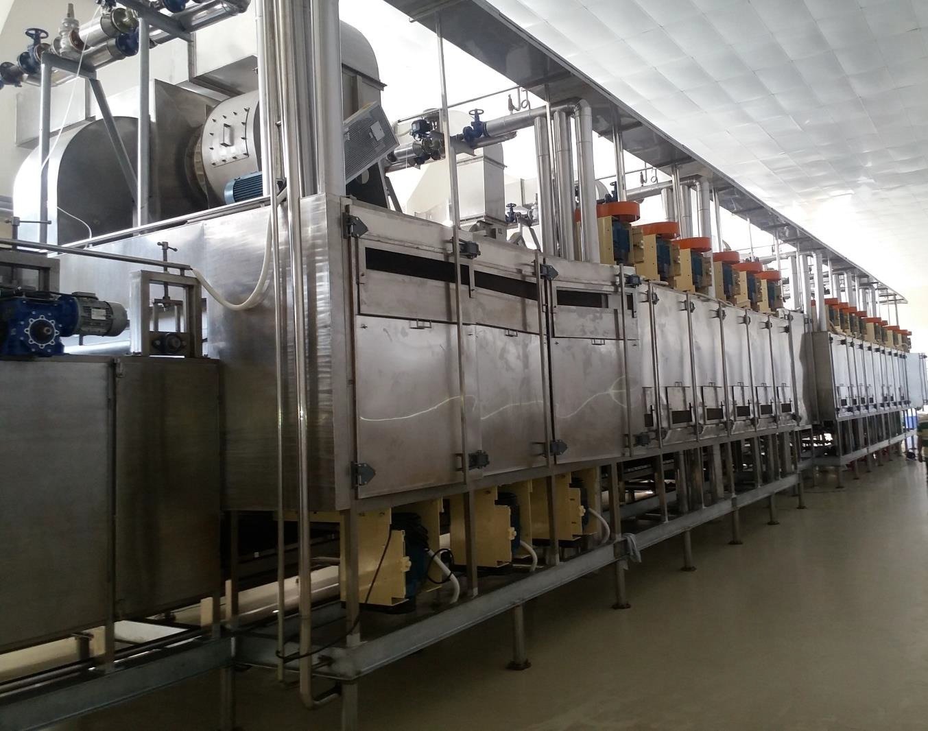
A PLC with a local HMI is enough for a single-product line with few recipes and simple reporting. SCADA becomes worthwhile with several products, several dryers or upstream and downstream machines to coordinate, and when the owner needs trends, batch or shift reports, energy tracking or audit trails. GTI’s band dryer page lists manual, PLC and SCADA control options.
| Need | Manual / relay | PLC + HMI | PLC + SCADA |
|---|---|---|---|
| Single product, steady feed | Possible | Suitable | Usually more than needed |
| Several products and recipes | Hard to control | Suitable | Suitable |
| Trends, reports, energy per kg | No | Limited | Suitable |
| Coordinating a full line | No | Possible | Suitable |
| Audit trail and access control | No | Basic | Suitable |
How should the control system be tested before start-up?
In two steps: a factory acceptance test (FAT) at the supplier’s works with simulated signals, and a site acceptance test (SAT) after installation with real instruments. The FAT proves sequences, interlocks, alarms and screens against the control philosophy. The SAT proves loop wiring, instrument ranges and actuator response on site before heat or product is introduced.
- Agree the FAT and SAT procedures and pass criteria in the contract.
- At FAT, test every interlock and sequence, including fault cases.
- At SAT, loop-check every instrument and actuator, and repeat the safety interlock tests.
- Tune control loops during hot commissioning, then record final settings.
- Hand over the final program backup, I/O list, loop drawings and the recipe sheet.
How can the control system track energy per kg of water?
By logging heat input and evaporation together. If steam flow, fuel use or thermic fluid heat is metered, and feed rate and moisture are known, the system can trend heat per kg of water evaporated. That one number shows fouling, air leaks, over-drying and poor heat recovery long before they appear on the fuel bill.
Worked example: heat per kg of water from logged data
Illustrative calculation, not data from any plant. A steam-heated belt dryer logs a steam flow of 2,100 kg/h. Saturated steam at about 7 bar(g) gives up roughly 2,050 kJ/kg when it condenses. The feed is 1,400 kg/h at 85% moisture and the product leaves at 6% moisture.
| Quantity | Calculation | Result |
|---|---|---|
| Heat input | 2,100 × 2,050 kJ/kg | about 4.31 GJ/h |
| Dry solids | 1,400 × (1 − 0.85) | 210 kg/h |
| Product | 210 ÷ (1 − 0.06) | about 223 kg/h |
| Water evaporated | 1,400 − 223 | about 1,177 kg/h |
| Heat per kg of water | 4.31 GJ/h ÷ 1,177 kg/h | about 3,660 kJ/kg |
Compared with a latent heat of about 2,400 kJ/kg, this example dryer uses about 1.5 times the minimum. Trending the figure each shift shows when it drifts. Product moisture below target is a common cause, because the dryer is evaporating water the customer does not need removed. For heat source options, see the GTI guide to choosing a dryer heat source.
Frequently asked questions
Rarely in the control loop. Most plants control a proxy such as outlet air temperature or exhaust humidity and confirm moisture by laboratory checks. Inline moisture meters help but must be calibrated against the laboratory method for each product.
When there are several products or dryers, upstream and downstream machines to coordinate, or a need for trends, shift reports, energy tracking and audit trails. A single-product line can usually run well on a PLC with a local HMI.
A factory acceptance test checks the control system at the supplier’s works with simulated signals. A site acceptance test checks wiring, instruments and actuators after installation, before heat or product is introduced.
For machinery placed on the EU market from 20 January 2027, yes. Annex III requires safety-related software and data to be protected against corruption and control systems to withstand foreseeable malicious attempts that could cause a hazard.
About Genex Tech Industries LLP (GTI Group)
Genex Tech Industries LLP (GTI Group) designs and manufactures industrial dryers, including band dryers, vibratory fluid bed dryers and spray dryers. Its published capabilities include PLC/SCADA automation systems, installation, commissioning and training. On this site, see our drying machines overview, the guide to belt dryer commissioning, and spray drying plant design. The head office is at 10C Middleton Row, Kolkata 700071, India.
Sources and authorship
- Regulation (EU) 2023/1230 on machinery, Official Journal of the European Union, adopted 14 June 2023; applies from 20 January 2027 (Annex III, sections 1.1.9 and 1.2.1).
- European Commission, “Machinery” (Internal Market, Industry, Entrepreneurship and SMEs), accessed November 2026.
- Published band dryer, VFBD, spray dryer, about-us and heat source pages of Genex Tech Industries LLP (GTI Group).
The worked example is an illustrative calculation from stated assumptions, using approximate steam table values. This article was prepared by the editorial team of Genex Tech Industries LLP (GTI Group) with AI editorial assistance. It has not been reviewed by a named engineer, and no individual is cited as having approved the technical content. It is not legal advice on EU regulation.
Next step
Specifying the control system for a new drying line, or upgrading an old one? Email mktg@gtidryers.com or use the contact page. Send your dryer type, products and number of recipes, heat source, upstream and downstream equipment, data and reporting needs, and the installation location.